


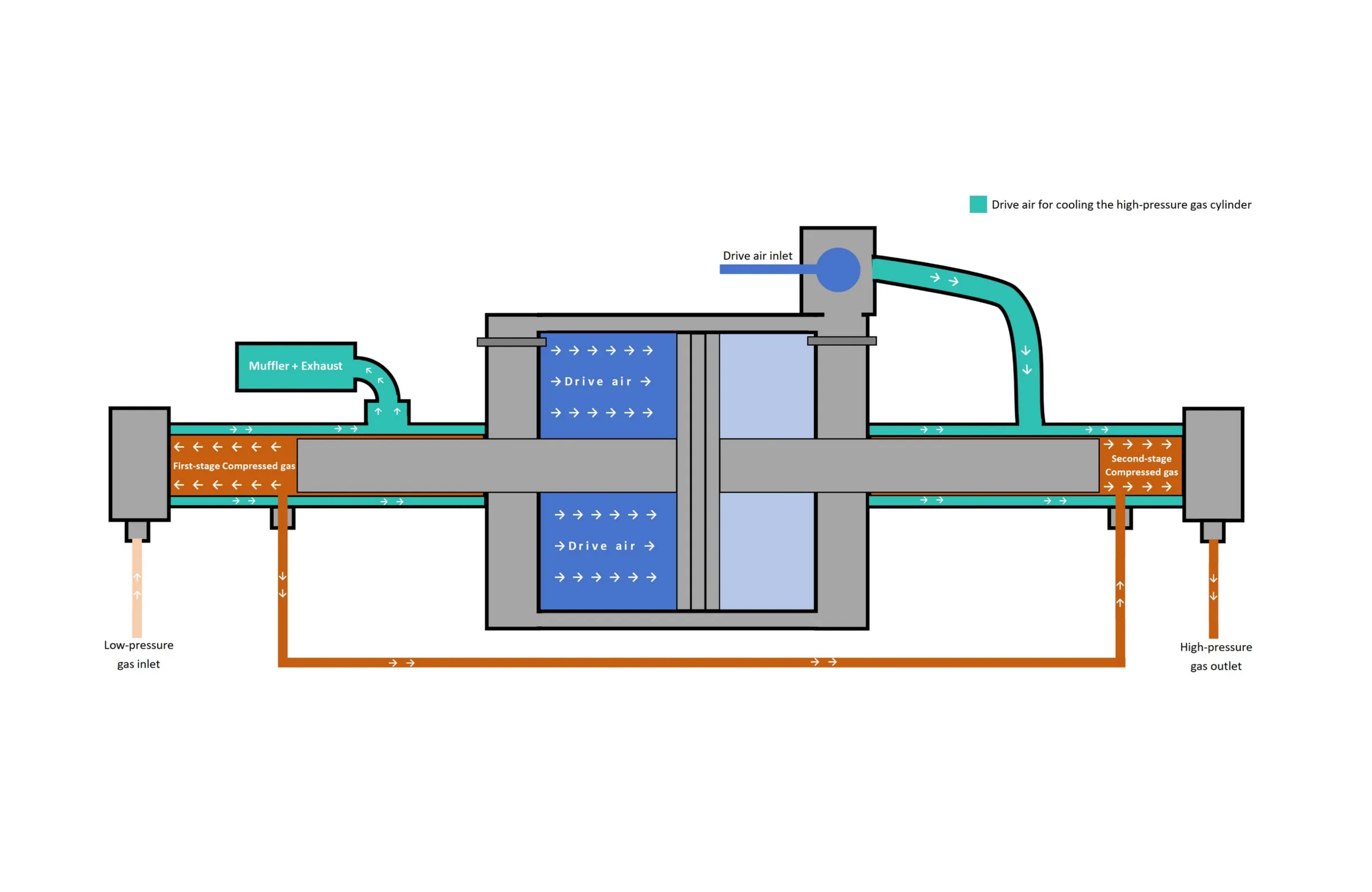
A pneumatic double-stage (or two-stage) booster pump uses sequential, series compression to achieve extremely high pressure ratios that single-stage boosters cannot reach efficiently.
While a standard double-acting pump uses two identical high-pressure chambers working in parallel to double flow, a double-stage booster uses two chambers of different sizes connected in series to multiply pressure in two successive steps.
The Core Principle: Serial Pressure Multiplication:
In a two-stage booster, a single central air drive piston drives two high-pressure plungers of different diameters mounted on opposite ends of a shared shaft:
Stage 1 (Low-Pressure / High-Volume Stage): Has a larger plunger diameter. It receives low-pressure gas from the supply source and compresses it to an intermediate pressure.
Stage 2 (High-Pressure / Low-Volume Stage): Has a smaller plunger diameter. It receives the pre-pressurized gas from Stage 1 and compresses it to the final target pressure.
Pressure Formula & Force Equilibrium:
The central drive piston applies equal force to both ends of the shared shaft. The force balance across the system governs the two stages:
Because Stage 2 starts compressing gas that is already pre-pressurized by Stage 1 (rather than ambient or low-pressure gas), the final output pressure (Pout) can reach extreme levels—often over 1,500 bar (21,700 psi)—even from a low supply pressure.
Step-by-Step Working Cycle:
1. Stroke A (Stage 1 Compression & Stage 2 Suction):
Initial intake into Stage 1. Driven air moves the central piston toward Stage 1 (the larger plunger).
Stage 1: Compresses incoming supply gas to an intermediate pressure level and transfers it through an inter stage line into Stage 2
Stage 2: Retracts, creating a vacuum that draws in this pre-pressurized intermediate gas from Stage
2. End-of-Stroke Reversal:
Directional spool shift
The piston hits a mechanical pilot valve at the end of Stroke A. The main directional air valve shifts, switching drive air to the opposite side of the central piston.
3. Stroke B (Stage 2 Compression & Stage 1 Suction):
Final compression to target pressure
Drive air moves the central piston toward Stage 2 (the smaller plunger)
Stage 2: The smaller plunger exerts massive force on the already pre-pressurized gas, compressing it to the ultra-high final output pressure (Pout) and discharging it into the high-pressure system.
Stage 1: Simultaneously retracts, opening its inlet check valve to draw in fresh gas from the low-pressure supply source
4. Cycling or Auto-Stall:
Continuous loop or stall
The pump cycles continuously until downstream resistance equals the total force generated by the drive air piston. Once target pressure is reached, the pump automatically stalls and maintains static pressure with zero air consumption.
Comparison: Single-Stage vs. Double-Stage Booster
| Feature | Single-Stage Booster | Double-Stage Booster |
|---|---|---|
| Compression Method | Parallel / Single Step | Series (Sequential Step 1 → Step 2) |
| Ideal Supply Pressure | Requires higher inlet gas pressure | Can start with very low inlet gas pressure |
| Plunger Configuration | Identical diameter plungers (if dual head) | Unequal plunger diameters (Stage 1 > Stage 2) |