


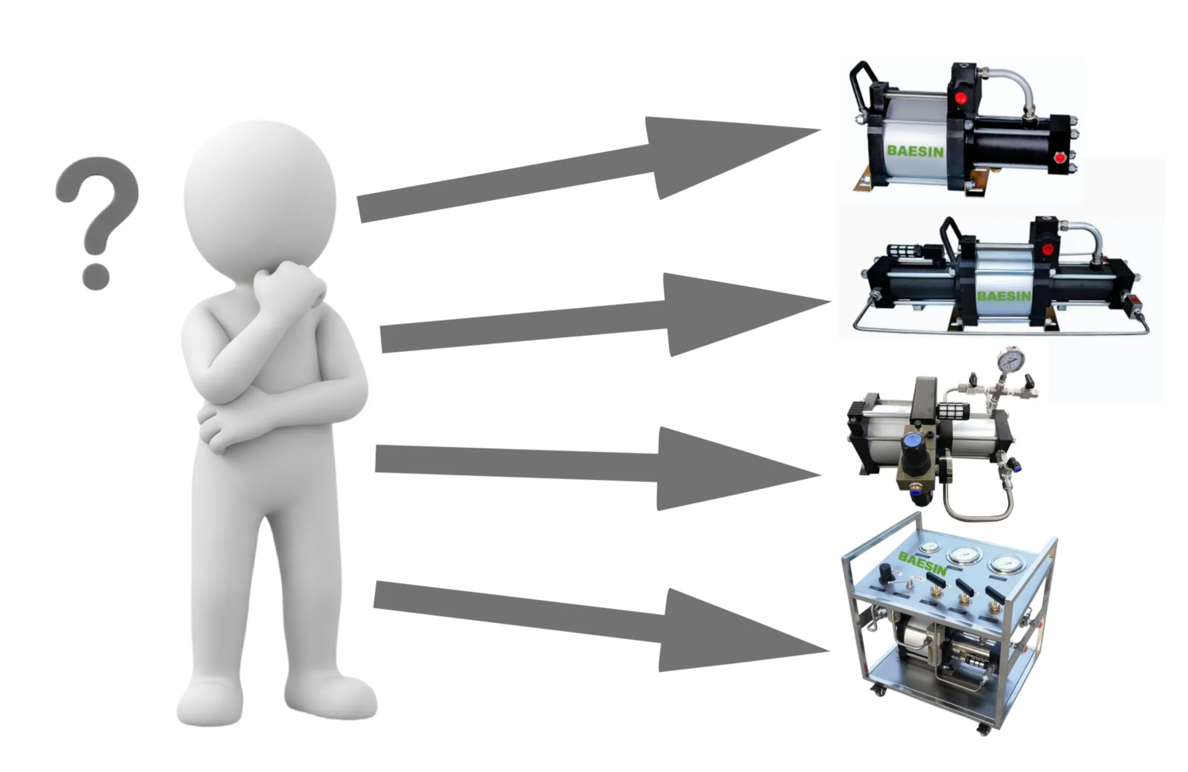
Selecting the right pneumatic booster system requires evaluating key operational variables across two primary phases: Media & Operating Parameter Analysis and System Integration & Accessory Configuration.
Phase 1: Media & Operating Parameter Analysis
1. Medium Characteristics & Material Compatibility
| Medium | Classification & Fluid Type | Key Material & Engineering Considerations |
|---|---|---|
| Gases | Inert / Neutral (Nitrogen, Helium, Argon, Air) | Standard stainless steel (e.g., 304SS) or aluminum components |
| Flammable / Explosive / Strongly oxidizing (Hydrogen, Methane, Natural Gas, Oxygen) | Static-conductive seals, and non-sparking materials. | |
| Corrosive / Reactive (Hydrogen Sulfide, Acid Gases) | Corrosive gases require 316 or higher grade stainless steel | |
| Liquids | Water / Aqueous Media | Requires corrosion-resistant stainless steel wetted parts and PTFE seal kits to prevent rust and cavitation wear. |
| Mineral / Synthetic Oils | Compatible with standard carbon steel or basic stainless steel wetted parts; Buna-N/NBR seals are generally sufficient. | |
| Chemical Media (Solvents, Acids, Alkalis) | Demands precise elastomeric compatibility (Viton, FFKM/Kalrez, EPDM) based on chemical concentration and temperature to prevent seal degradation. |
2.Pressure & Flow Parameters:
- Maximum Required Pressure (Ptarget): Determines the booster's pressure multiplication ratio (i). Choose a model whose max output exceeds your target working pressure by 20–30% to ensure reliable long-term performance.
- Inlet Pressure Conditions (Pinlet):
Gas Applications: Gas inlet pressure dictates whether a single-stage, double-acting, or double-stage booster is required.
If supply gas pressure is low or decreases as a storage bottle empties, a double-stage booster is needed to maintain output pressure and high compression efficiency.
Liquid Applications: Liquids are generally non-compressible and fed at atmospheric pressure (0 bar) or low gravity feed.
- Flow Rate Requirements (Qrequired): Define whether the application requires rapid filling or steady pressure maintenance.
Liquid flow is measured in liters per minute (L/min), while gas flow should be specified in normal liters per minute (NL/min) or standard cubic feet per minute (SCFM).
3. Drive Air Supply Specifications (At Application Site)
The pneumatic drive supply directly dictates the output capacity and cycling frequency of the pump.
- Drive Air Supply: Specify available site pressure (typically 3-8 bar) and available air flow(800-1,000 L/min)
- Sizing Rule: If site air is limited, the booster's cycling rate will slow down, resulting in lower high-pressure output flow. If site air supply parameters are unavailable, size an auxiliary air compressor capable of delivering 6-8 bar continuous pressure at 800-1,000 L/min flow.
4. Specific Application Requirements
Gas Applications:
- Gas Cylinder Filling: Requires high boost ratios, double-stage pumps to handle declining inlet pressures, and overpressure relief protection.
- Production Line Pressurization: Requires continuous duty cycling, high pulsation dampening, and stable pressure regulators.
- Leak / Burst Testing: Requires fine pressure control, hold capability at target pressure, and fast response times.
Liquid Applications:
- Hydrostatic Pressure Testing: Demands precise pressure hold capabilities and high-pressure release/bleed valves.
- Chemical Injection / Filling: Requires metered volume control, corrosion-resistant dynamic seals, and chemical-duty check valves.
- Liquid Transfer / Flushing: Prioritizes high continuous flow rate over extreme pressure ratios (often utilizing double-acting liquid pumps).
Phase 2: System Accessories & Level of Integration
Depending on the operational setup, pneumatic boosters range from bare-pump components to fully automated power units.
Option A: Bare Pump Only (Component Level)
- Scope: Booster pump only.
- Customer Requirements: The integrator/end-user must supply and install drive air filtration/regulation units, high-pressure needle valves, isolation valves, calibrated pressure gauges, high-pressure tubing/fittings, and overpressure safety relief valves.
Option B: Packaged Pneumatic Power Unit (Standard Manual Skid)
- Scope: Fully assembled, turn-key portable or frame-mounted skid.
- Included Components:
- Heavy-duty stainless steel frame/panel.
- Air drive control package (FRL unit: Filter, Regulator, Lubricator/Oil-Free Valve, On/Off valve, Drive Gauge).
- High-pressure inlet and outlet isolation valves, bleed/vent valves, and stainless steel interconnecting piping.
- High-pressure outlet pressure gauge and safety relief valve.
Option C: Advanced / Automated Control System
- Scope: Semi-automatic, fully automatic, or digitally integrated testing & filling rig.
- Enhanced Capabilities:
- Automated Control: Solenoid valves, electro-pneumatic pressure regulators, and PLC-based target pressure auto-shutoff.
- Data Acquisition & Export: High-precision pressure transducers, digital chart recorders, data-logging software with USB/Ethernet export for test certification.
- Remote Operation & Safety: Remote START/STOP interface, emergency stop integration, and blast-screen enclosure interlocks.
- Form Factor & Ergonomics: Custom footprint restrictions, mobile wheeled carts, or sound-attenuated cabinet enclosures.